Mode of Operation
Creating real and virtual worlds
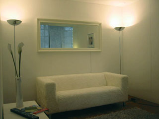
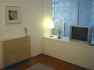
Furnishing the real world
A trip to IKEA makes it possible. The living-room looks no longer like a laboratory. Since there are no more patterns needed for optical spatial tracking, the walls can be covered as well.
Reconstructing a virtual version of the real world
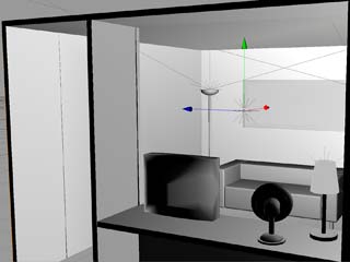
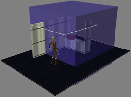
The entire living room including all furniture needs to be available as an accurate 3D model to allow realistic rendering of virtual objects (for example virtual objects casting shadows on real objects, real objects occluding virtual objects etc.). This was done in Cinema4D and 3D Studio Max.
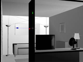
First scenarios created with a simulator
The modeled living room was imported into Virtools and allowed us to create first simulations of scenarios (pure VR-scenarios with a virtual avatar, controllable with keyboard and mouse). The pictures show an external view of the avatar in the living room and the "first-person" view of the avatar.
Merging real and virtual worlds
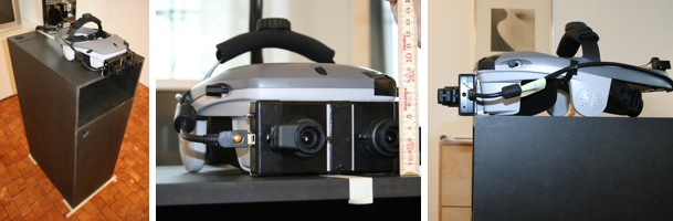
Basic stereoscopic camera see-through setup and calibration
For stereoscopic viewing in the Virtools VR Player, a single virtual camera is modeled as two cameras with identical focal lengths and orientation. Each camera is horizontally displaced to the left or right of the single virtual camera by half the interpupillar distance (IPD). The real-world cameras are set up and mounted to the HMD in the same manner. Due to the casing of the cameras used, the distance between the real cameras could not be less than 75mm, even when the cameras were mounted with no gap between the casings. The IPD was thus set to the same value of 75mm, which is slightly more than usual IPD values (63mm is a widely used standard value). Nevertheless, the stereoscopic effect was tested in a VR-scenario and proved to be quite satisfactory, although slightly exaggerated.
In principle, the basic real-world view (we call this the AR backdrop) can now be obtained by displaying the image of the left camera on the left eye's display and the right camera on the right eye. However, the unprocessed camera images to not correspond to an exact stereoscopic image due to mechanical tolerances and unavoidable imprecisions in the mounting of the cameras. Therefore a more sophisticated setup on the software side is needed to obtain a satisfactory stereoscopic image.
- The camera inputs are mapped in real-time to 3D textures which are in turn mapped to the materials of two 3D sprites. Each sprite is only rendered to the display of one eye. These rectangular sprites are sized and positioned relative to the virtual cameras so that the rendered sprite appears slightly larger than the display of the respective eye.
- To
obtain a correct stereoscopic image, the sprites are rotated (using the
respective virtual camera's position as the center of rotation) to make
the necessary corrections (horizontal / vertical shifting and roll). The
following calibration procedure was used:
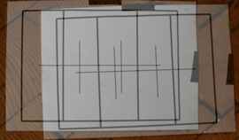
A reference pattern (see image below) was placed in front of the cameras. Both backdrop sprites were then rendered on to a single display in a semi-transparent manner. This made it easy to see when the two images overlap to a correct stereoscopic image. The corrections were made interactively inside the Virtools development environment. - Additionally, the camera parameters (focus, iris, gain, contrast, white balance) were set manually to ensure that the images for both eyes are as similar as possible.
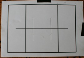
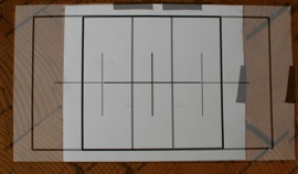
Left: Reference pattern for stereo calibration.
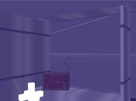
Below left: Incorrect overlap.
Below right: Correct stereo overlap after corrective rotations.
Putting real and virtual views together
In the Virtools setup, the input from the head tracker is mapped to the position and orientation of a 3D coordinate system. The offset between the head-tracker and the camera is measured (on the real HMD) and transferred to a fixed offset between the tracker reference coordinate system and the virtual camera.
This tracker/camera/backdrop system can be placed into the simulator scenarios to achieve a superimposition of virtual and real worlds. To fine-tune the overlap of virtual and real objects, the virtual models can be rendered with a wire-frame outline.
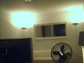
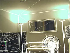
Eventually the models of the real-world objects are no longer rendered, leaving an image composed of the real-world backdrop and virtual objects. The models of real-world objects can still occlude virtual objects (if a virtual object is placed behind a real object, the AR backdrop will appear "in front" of the virtual object within the outline of the real object).
Final calibration
To achieve the best possible congruence between real and virtual worlds, an additional calibration procedure was undertaken: The HMD was placed on a wooden pedestal in the center of the living room facing the rear wall. The position of the tracker and the orientation of the HMD were measured as accurately as possible by hand using rulers and leveled using a spirit-level. Reference points were marked on the rear wall, and also were added to the 3D model. Minor adjustments were now made to make the virtual model match the real image as well as possible.